
Three-dimensional printed circuit boards make optimum use of the limited installation space and can be constructed using various processes, assembly variants and materials. With rigid-flex, semiflex and HSMtec 3D, we present three manufacturing processes and highlight their technical properties, possible applications as well as their advantages and limitations.
Increasing packing density, reducing weight and at the same time increasing the reliability of assemblies – three-dimensional printed circuit boards are being used in more and more products. The ability to directly connect parts of a circuit on different PCBs or PCB segments replaces connectors and cables. In addition, 3D PCBs open up new design possibilities and help reduce system costs.
A characteristic feature is that the printed circuit boards are designed as a two-dimensional board, manufactured in the panel and assembled. Only after assembly is the printed circuit board bent into its three-dimensional shape. A distinction is made between one-time bending for assembly, a few bends e.g. in use or continuous bending e.g. for high bending cycles in use.
Rigid-flex PCB: versatile geometries and layouts
Rigid-flex PCBs are the preferred and optimal solution when several rigid PCBs are to be electrically connected in different mounting positions and orientations. The parts of the circuit are distributed over several rigid circuit carriers and interconnected via a flexible polyimide PCB foil. The flexible film is integrated into the layer structure of the connected printed circuit boards. The flexible and rigid parts are connected via electrical. At the bending points, the FR4 material is milled down to the flex foil. The thin polyimide guarantees maximum three-dimensional adaptability to limited space conditions. The space required for the printed circuit board can be “folded away”, so to speak.
Rigid-Flex technology is very versatile in terms of arrangement options and geometries. Other advantages: Eliminating many solder joints, cables, wires, jumpers and connectors not only minimizes space and weight, but also eliminates potential sources of error and reduces overall costs. However, with the thin materials of the flexible printed circuit board part, bending radii and bending cycles must be taken into account.
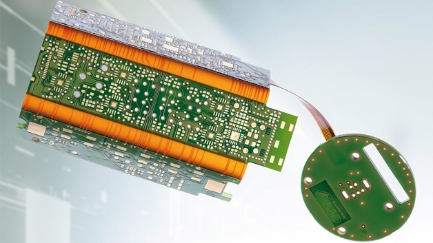
One example: The compact housing of the Power-Check tool clamp from Ott-Jakob in Allgäu fits into the tool magazines of all machine manufacturers. The tool clamp checks the force with which the tool is pulled into the spindle cone of the machine tool. If the force falls below a certain threshold, there is a risk of increased tool wear or vibrations that leave unclean machining marks on a workpiece. The Power-Check checks not only the force: when setting up a new motor spindle, different tolerances for tools of different lengths can be simulated. In addition, digital switching outputs can be programmed for clear signal messages about whether a tool is well or poorly clamped.
The sophisticated design is realised in a four-layer rigid-flex multilayer – just 122.89 mm long and 70.15 mm wide – with an electroless nickel-gold surface, which connects four rigid parts with, among others, a flex part that lifts off. On it are, among other things, a microcontroller, a measuring device amplifier, several magnetic switches, LEDs for the display, a complete front end for radio transmission and a lithium cell as energy storage.